
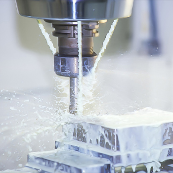
Milling cutter basics
First, the basic requirements of the cutting part of the milling cutter material
(1) High hardness and wear resistance: at room temperature, the cutting part must have sufficient hardness to cut into the workpiece; with high wear resistance, the tool will not wear out and prolong its service life.
(2) Good heat resistance: the tool will generate a lot of heat during the cutting process, especially when the cutting speed is high, the temperature will be very high. Therefore, the tool material should have good heat resistance, both at high temperatures can still maintain a high hardness, but also has the ability to continue cutting. This high temperature hardness characteristic is also known as hot hardness or red hardness.
(3) High strength and toughness: the tool must withstand a large impact during cutting, so the tool material must have high strength, otherwise it is easy to break and damage. As the milling cutter will be subject to impact and vibration, so the material of the milling cutter should also have good toughness, not easy to collapse and chipping edge.
2、Milling cutters commonly used materials
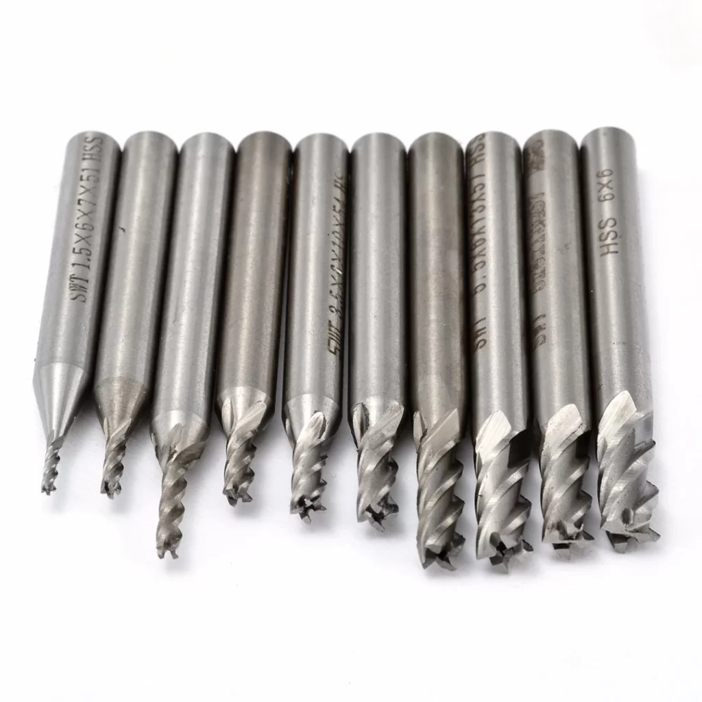
(1) high-speed tool steel (referred to as high-speed steel, sharp steel, etc.), divided into general high-speed steel and special high-speed steel. It has the following characteristics:
A. Alloy elements tungsten, chromium, molybdenum, vanadium content is high, quenching hardness up to HRC62-70. in 6000C high temperature, can still maintain a high hardness.
B. Good edge strength and toughness, strong shock resistance. Can be used to make tools with average cutting speed. For less rigid machine tools, HSS milling cutters can still cut smoothly.
C. Good process performance, forging, machining, sharpening are relatively easy, can also be manufactured complex shape of the tool.
D. Compared with carbide materials, there are still disadvantages such as lower hardness, red-hardness and poor wear resistance.
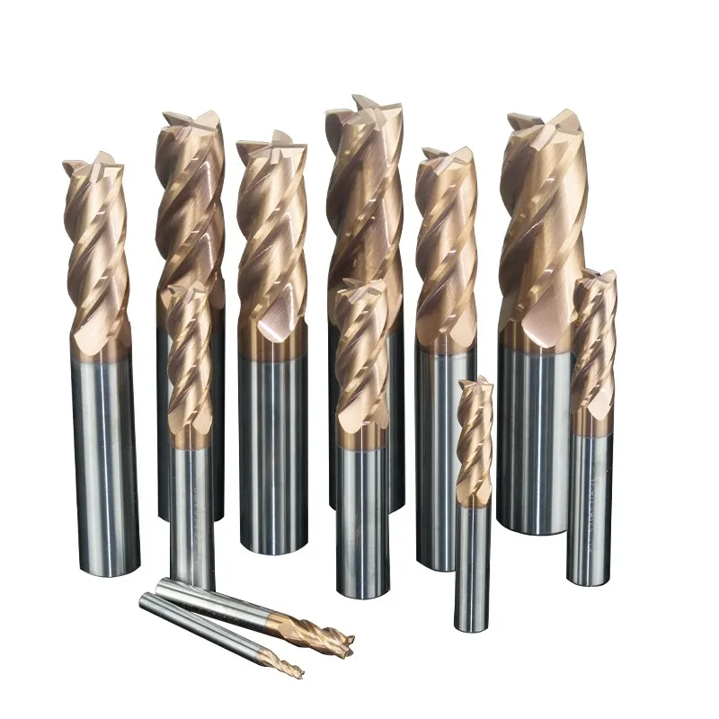
(2) Cemented Carbide: made of metal carbide, tungsten carbide, titanium carbide and cobalt based metal bonding agent by powder metallurgy process. Its main characteristics are as follows:
High temperature resistance, in about 800-10000C can still maintain good cutting performance. The cutting speed can be chosen 4-8 times higher than HSS when cutting. High room temperature hardness and good wear resistance. Low flexural strength, poor impact toughness, blades are not easy to sharpen.
The commonly used carbides can generally be divided into three categories:
① Tungsten Cobalt Cemented Carbide (YG)
Commonly used grades are YG3, YG6, YG8, where the number indicates the percentage of cobalt content. The higher the cobalt content, the better the toughness and the more resistant to shock and vibration, but the hardness and wear resistance will be reduced. The alloy is therefore suitable for cutting cast iron and non-ferrous metals, but can also be used for cutting rough and hardened high-impact steel and stainless steel parts.
② Titanium Cobalt Cemented Carbide (YT)
Common grades are YT5, YT15, YT30, with the numbers indicating the percentage of titanium carbide. Carbide containing titanium carbide can increase the bonding temperature of steel, reduce the friction coefficient, slightly increase hardness and wear resistance, but reduce flexural strength and toughness, and make the performance brittle. The alloy is therefore suitable for cutting steel parts.
③ General purpose carbide
Adding the right amount of rare metal carbides such as tantalum carbide and niobium carbide to the above two carbides refines the grain and improves its room temperature and high temperature hardness, wear resistance, bonding temperature and oxidation resistance, which can increase the toughness of the alloy. As a result, these carbide tools have better overall cutting performance and versatility. Machining high strength steel, heat resistant steel, stainless steel and other materials.
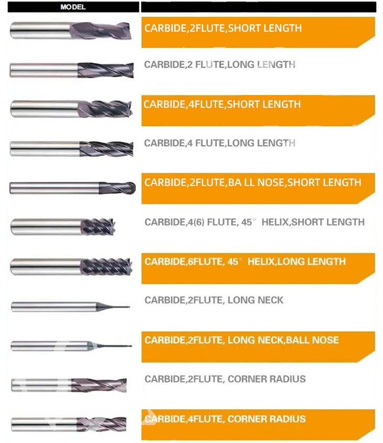
Three, the type of milling cutter
(1) according to the material of the cutting part of the milling cutter:
A. high-speed steel milling cutter: for more complex tools.
B. Carbide milling cutter: Most of them are fixed on the cutter body by welding or mechanical clamping.
(2) Divided by milling cutter usage:
A. Milling cutters for processing flat surfaces: cylindrical milling cutters, end mills, etc.
B. Milling cutters for processing grooves (or steps): end mills, disc milling cutters, saw blade milling cutters, etc.
C. Milling cutters for shaped faces: shaped milling cutters, etc.
(3) According to the structure of the milling cutter
A. Sharp tooth milling cutter: the truncated shape of the back of the tooth is straight or folded, easy to manufacture and sharpen, the cutting edge is sharper.
B. Spade tooth milling cutter: the back of the tooth is cut off in the shape of Archimedes screw line. This kind of milling cutter after sharpening, as long as the front angle remains unchanged, the tooth shape also remains unchanged, suitable for molding milling cutter
4, the main geometric parameters of the milling cutter and the role
(1)The name of each part of the milling cutter
① Base surface: through any point on the tool and perpendicular to the point cutting speed plane.
② Cutting plane: through the cutting edge and perpendicular to the plane of the base surface.
③ Front face: the plane from which the chips flow.
④ Back tool face: the face opposite to the machined face
(2) The main geometric angles of the external milling cutter and their functions
① Front angle Γ0: the angle between the front tool face and the base surface. The effect is that the cutting edge is sharp, reducing the deformation of the metal during cutting, and the chips are easily discharged, thus saving cutting force.
②Back angle Α0: the angle between the rear tool face and the cutting plane. Its main role is to reduce the friction between the rear tool face and the cutting plane, reducing the surface roughness of the workpiece.
③ rotation angle 0: the angle between the tangent line on the oblique tooth insert and the axis of the milling cutter. The function is to make the cutter teeth cut into and out of the workpiece step by step in order to improve cutting stability. At the same time, for the external milling cutter, there is the role of making the chips from the end face smoothly out.
(3) The main geometric angle of the end mill and its role
The end mill has an additional secondary cutting edge, so in addition to the front and rear angles, there are:
① Main offset angle Kr: the angle between the main cutting edge and the machining surface. Its variation affects the length of the main cutting edge involved in cutting, changing the width and thickness of the chip.
② Sub-deviation angle Krˊ: the angle between the sub-cutting edge and the machining surface. The effect is to reduce the friction between the secondary cutting edge and the machined surface, and to influence the effect of the secondary cutting edge on the finish of the machined surface.
③ ③ Angle of inclination Λs: the angle between the main cutting edge and the base surface. It mainly plays the role of bevel cutting.
5. Milling cutter
Forming milling cutters are special milling cutters used for machining formed surfaces. The cutting edge profile needs to be designed and calculated according to the contour of the workpiece to be machined. It can be used on general-purpose milling machines to machine complex surfaces with a consistent shape and high efficiency. It is widely used in mass production and mass production.
(1) Forming milling cutters can be divided into two types of sharp teeth and spade teeth
Milling and resharpening of sharpening cutters requires a special tooth shape, which is difficult to manufacture and sharpen. The back of the teeth of the shovel tooth forming milling cutter is sharpened and sharpened on the shovel tooth lathe. When resharpening, only the front cutter face is ground. Because the front face is flat, it is easier to grind the cutter. At present, the shovel tooth structure is mainly used for profile milling cutters. The back side of the shovel tooth should meet two conditions: ① the shape of the edge remains the same after resharpening; ② the required back angle is obtained.
(2) Tooth back curve and equation
The intersection of the end section perpendicular to the axis of the cutter through any point on the cutting edge of the cutter and the back surface of the tooth is called the back curve of the cutter.
The back of the tooth curve should meet two main conditions: firstly, the back angle of the cutter is basically unchanged after each resharpening; secondly, it is simple to manufacture.
The only curve that can satisfy a constant back angle is the logarithmic helix, but it is difficult to manufacture. The Archimedean spiral can satisfy the requirement of a substantially constant back angle and is simple to manufacture and easy to implement. For this reason, Archimedean spirals are widely used in production as tooth back curves for profile milling cutters.
According to geometric knowledge, the value of the vector radius Ρ at each point on the Archimedean spiral increases or decreases in proportion to the value of the vector radius rotation angle Θ.
Therefore, by combining a constant rotational motion with a constant linear motion along the radial direction, an Archimedean spiral can be obtained.
Expressed in polar coordinates: Ρ=R when Θ=00, (R is the radius of the milling cutter), Ρ<R,< P=””></R,<> when Θ>00
The general equation for the back of the milling cutter teeth is: Ρ=R-CQ
Assuming that the shovel does not return, the shovel tooth volume is K for each inter-tooth angle Ε = 2π/Z of the milling cutter rotation, and accordingly the cam lift volume should be K. To allow for uniform blade movement, the curve on the cam should be an Archimedean screw line for ease of manufacture. In addition, the cam size is determined only by the shovel volume K, independent of the milling cutter diameter and the number of teeth and back angle. As long as the production volumes are equal, the cams can be used universally. This is the reason why Archimedean spirals are widely used for the back of the teeth of shovel-forming milling cutters.
Knowing the radius of the milling cutter R and the cutting volume K, it follows that C
When Θ = 2π/Z, Ρ = RK
Then RK = R-2πC /Z ∴ C= Kz/2π
6, milling cutter dull will appear after the phenomenon
(1) From the shape of the chip, the chip becomes thick and flaky. As the chip temperature rises, the chip colour becomes purple and smokes.
(2) The surface roughness of the workpiece is very poor, and there are bright spots such as gnaw marks or ripples on the surface of the workpiece.
(3) Severe vibrations and strange noises are generated during the milling process.
(4) From the shape of the cutter, there are bright white spots on the cutter.
(5) When milling steel parts with carbide milling cutters, a large amount of fire mist often flies out.
(6) When milling steel parts with HSS milling cutters, a large amount of smoke will be generated if oil is used for lubrication and cooling.
When the milling cutter is dull, it should be stopped in time to check the wear of the milling cutter. If the wear is slight, the edge can be ground with an oil stone before use; if the wear is severe, it must be ground fast to prevent excessive wear.
About Us
We have been engaged in precision manufacturing since 2000, and we are committed to personnel training, product development, technology development and equipment renewal, steadily growing into one of the outstanding companies in China for precision tools.
Address
- Tel: 0539-4687610
- Skype:(+1)2134255500
- E-mail:eva@densotool.com
- WhatsAPP:(+1)2134255500
- Telegram: https://t.me/densotoolsoem
- Address: Taihe Road, Dongcheng Development Zone, Pingyi County, Linyi City, Shandong Province,China